
Explore our high-efficiency, fully compliant brushless and stepping drive motor series. Built with industrial-grade insulation, precise microstepping controllers, and robust thermal engineering.
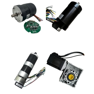
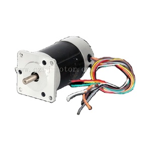
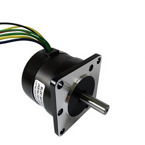
In high-precision automated systems—ranging from semiconductor wire bonders and medical peristaltic pumps to multi-axis CNC gantries—the choice of motion controller dictates systemic positioning accuracy, thermal dissipation profiles, and acoustic resonance signatures. As a premier micro stepper drives factory and international exporter, our engineering paradigm centers on optimizing sinusoidal current distribution within hybrid stepping motor windings to achieve sub-micron incremental resolution.
Standard full-step or half-step excitation topologies induce discrete rotor jumps, causing mechanical shock, high torque ripple, and severe mid-band resonance. Microstepping technology mitigates these dynamic anomalies by dividing a full 1.8° step (200 full steps per revolution) into micro-steps (up to 51,200 micro-steps per revolution or 1/256 step resolution). This is achieved through dual Pulse-Width Modulation (PWM) H-bridge drivers regulating phase currents $I_A$ and $I_B$ in according to quadrature trigonometric functions:
One of the core technological breakthroughs incorporated into our modern micro stepper drives is active electronic damping. Stepper motors inherently operate as spring-mass systems subject to natural frequency oscillation, particularly between 50 RPM and 150 RPM. Our advanced digital signal processors (DSPs) continuously analyze back-EMF phase signals to calculate real-time velocity ripple, injecting reverse-phase corrective currents to suppress mid-band instability automatically.
Cost-effective, highly reliable architecture ideal for constant-load applications where positioning stall detection is not critical. Provides precise position control without encoder feedback lines, minimizing cable complexity.
Integrates high-resolution optical or magnetic encoders (1000 to 4096 PPR). The drive operates as a 2-phase brushless servo system, supplying current dynamically based on actual load demand, eliminating lost steps and reducing power dissipation by up to 40%.
Selecting the correct drive topology requires matching continuous torque requirements, dynamic operating voltage, peak current capability, and fieldbus communication standards. The matrix below illustrates typical engineering parameters for our industrial micro stepping drive lines:
| Series Category | Operating Voltage | Peak Output Current | Max Microstep Division | Control Interfaces | Primary Industrial Use-Case |
|---|---|---|---|---|---|
| Compact LV-Series | 12 – 48 VDC | 0.5 – 3.0 A RMS | 1/128 Step | PUL/DIR, CW/CCW | Medical Instruments, 3D Printers |
| High-Voltage HV-Series | 24 – 110 VDC / 85-240 VAC | 1.4 – 8.2 A Peak | 1/256 Step | Modbus-RTU, CANopen | CNC Routers, Packaging Automation |
| Closed-Loop Hybrid Servo | 24 – 80 VDC | 2.0 – 6.0 A RMS | Adaptive Vector PWM | EtherCAT, CANopen | Robotic Arms, Pick-and-Place Gantry |
| Integrated Drive-Motor | 24 – 48 VDC | 1.0 – 4.5 A Peak | 1/64 Step | IO-Link, RS-485 | Conveyor Belts, AGV Steering Systems |
As global industrial automation shifts toward Industry 4.0 and Smart Manufacturing frameworks, procurement executives and control system designers must anticipate key technological transformations over the next decade. Sourcing strategies are moving away from standalone power stages toward intelligent, network-aware motion nodes.
Traditional Pulse/Direction hardware signals are rapidly being superseded by real-time fieldbus architectures such as EtherCAT, PROFINET, and CANopen. Drives now act as decentralized intelligence modules capable of executing onboard motion profiles (CiA 402 profile).
The adoption of Gallium Nitride (GaN) and Silicon Carbide (SiC) MOSFETs allows switching frequencies above 100 kHz. This yields ultracompact drive footprints, near-zero switching heat losses, and ultra-smooth coil current waveforms.
Modern micro stepper drives integrate sensorless load angle monitoring and winding thermal modeling. Drives transmit early warning diagnostics to cloud platforms before mechanical bearing failure or belt slippage occurs.
With over 120 years of rotating electrical machine experience, SAS T-T Electric (Headquartered at 22 rue du 8 mai 1945, F-95340 Persan, France) represents world-class European engineering rigor combined with scalable high-precision manufacturing. Our global supply chain network serves clients across more than 60 countries, providing custom-built DC motors, AC square frame motors, variable speed drives, and advanced micro stepper drive solutions.
Every micro stepper drive and motor assembly undergoes 100% automated End-of-Line (EOL) testing, including dynamic insulation resistance testing, high-voltage breakdown analysis, and thermal endurance profiling. Our factory operates under stringent quality management protocols certified by LRQA, and we hold active corporate memberships in leading trade associations including EASA and AEMT.
 T-T Electric Global Manufacturing & R&D Hub



Open-loop drives send step and direction signals to the motor without positional feedback. While highly economical, if mechanical overload occurs, the motor may slip or lose steps without the controller's knowledge. Closed-loop drives utilize encoder feedback to monitor actual shaft position, dynamically adjusting current vectors to prevent step loss, increase acceleration limits, and lower operating temperatures.
Microstepping increases positioning resolution and dramatically reduces low-speed vibration. However, the incremental holding torque between microsteps diminishes as microstep division increases. The incremental torque for a single microstep is given by $T_{inc} = T_{holding} \cdot \sin(90^\circ / N)$, where $N$ is the number of microsteps per full step. Overall continuous running torque remains high, but fine incremental positioning requires adequate torque margins.
To maintain motor torque at high RPMs, the supply voltage to the drive should be significantly higher than the motor's nominal rated voltage (typically 4x to 25x higher). The drive's constant-current PWM chopper manages winding current safely. High bus voltage overcomes the motor winding back-EMF, allowing faster current rise times during phase commutations.
Yes. In addition to traditional Pulse/Direction and CW/CCW command inputs, our digital drive series supports RS-485 Modbus-RTU, CANopen (CiA 402 profile), and EtherCAT protocols, enabling seamless integration into PLC and industrial IPC control environments.
Our drives feature heavy-duty extruded aluminum heatsinks and integrated thermal protection sensors that trigger alarm outputs if junction temperatures exceed safe thresholds. EMI mitigation is accomplished via internal opto-isolated signal inputs, differential control line receivers, and multi-layer PCB ground planes designed in compliance with CE and EMC directives.
Standard catalog drives and motors are available from stock or standard assembly lines within 1 to 2 weeks. Custom OEM projects—including customized firmware algorithms, specific wire harness connectors, and custom mounting flanges—typically ship within 4 to 6 weeks following prototype engineering sign-off.