
China Top Stator Core Laminations Manufacturers & Custom Sourcing Guide

Engineered Electrical Steel Stamping, Ultra-Low Loss Silicon Steel Laminations & Precision Stator Rotor Core Stacking Solutions for High-Efficiency Electric Motors and Transformers.

Featured Stator & Rotor Core Lamination Products

High-precision electrical steel laminations manufactured via ultra-high-speed progressive dies, custom bonding, and stress-relief annealing.
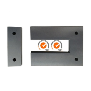
EI UI Shape Electrical Silicon Steel Lamination

EI UI Shape Electrical Silicon Steel Lamination for Transformer Core

Precision-punched EI and UI shape silicon steel sheets engineered for low hysteresis loss in transformers and toroid core stackers.
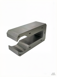
Silicon Steel Brushless Motor Core Lamination

High Quality Silicon Steel Brushless Motor Core Lamination Stack

High-precision BLDC rotor stator matching wire frame lamination stack with customizable shaft sizes up to 50mm length.
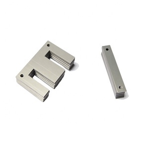
Magnetic Core Lamination EI 75 Silicon Steel

Magnetic Core Lamination EI 75 Silicon Steel Transformer Core

Standard and custom EI 75 magnetic core laminations optimized for maximum magnetic flux density and reduced copper loss.
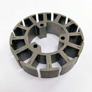
Custom Motor Stator Rotor Lamination

Custom Motor Stator Rotor Lamination & BLDC Punching Core

Tailor-made silicon steel sheet lamination and progressive stamping for BLDC motors, servo actuators, and generators.
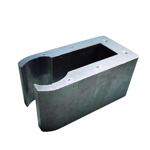
Customized Silicon Steel Motor Stator Core U010

Customized Silicon Steel Motor Stator Core U010 Servo Laminations

Precision engineered U010 brushless servo motor laminations featuring ultra-tight concentricity tolerances and custom shaft configurations.
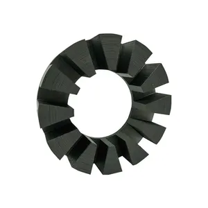
Customized Engine Stator Core Laminations

Customized Engine Stator Core Laminations & Stator Stacks

Heavy-duty engine stator lamination assemblies built for automotive, industrial machinery, and high-vibration applications.
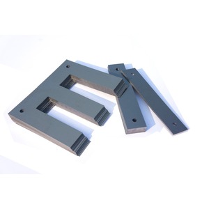
EI Silicon Steel Sheet Stator Iron Core

EI Silicon Steel Sheet Stator Iron Core Lamination for Transformer

High-permeability cold-rolled non-oriented and grain-oriented silicon steel transformer lamination stacks for power conversion.
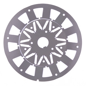
Household Electrical Appliances Motor Core Lamination Stack

Household Electrical Appliances Motor Core Rotor & Stator Stack

Cost-optimized, mass-produced lamination stacks for HVAC compressors, washing machines, pumps, and home appliance motors.

120+
Years Combined Engineering
<0.02mm
Stamping Tolerance Precision
0.1 - 0.5mm
Silicon Steel Thickness Spectrum
ISO/IATF
Quality Management Certified

Technical Whitepaper: Precision Stator Core Laminations Engineering & Sourcing

Stator and rotor core laminations represent the electromagnetic heart of electric motors, generators, and transformers. As global industrial manufacturing shifts toward higher efficiency ratings (IE4 and IE5 standards), Electric Vehicle (EV) electrification, and ultra-high-speed Brushless DC (BLDC) systems, selecting the right China top stator core laminations manufacturer has become a vital strategic imperative for OEM purchasing teams and electrical engineers alike.

This technical guide evaluates the metallurgical properties, manufacturing technologies, stacking methodologies, and procurement parameters required to achieve peak electromagnetic performance while minimizing total manufacturing cost.

Information Gain Highlight: Reducing lamination thickness from 0.50mm (35WW500 grade) to 0.20mm (20WW1200 ultra-thin grade) reduces high-frequency eddy current losses by up to 64% at 400Hz, enabling high-RPM BLDC motors to maintain thermal stability and achieve system efficiencies above 96%.

1. Silicon Steel Metallurgy and Electromagnetic Loss Analysis

The magnetic performance of a motor lamination core is primarily governed by the quality of the cold-rolled electrical silicon steel (CRNGO and CRGO) used in production. Core losses ($P_{core}$) consist of two main components: Hysteresis loss ($P_h$) and Eddy current loss ($P_e$).

Mathematically expressed via the Steinmetz equation:

P_{core} = P_h + P_e = K_h \cdot f \cdot B_{max}^n + K_e \cdot f^2 \cdot t^2 \cdot B_{max}^2

Where f represents operating frequency, Bmax is peak magnetic flux density, and t is the lamination sheet thickness. Minimizing the sheet thickness t exerts a quadratic reduction effect on eddy current losses, making thin-gauge silicon steel essential for modern high-frequency motors.

Comparison Matrix: Electrical Steel Grades & Application Parameters

Steel Grade (IEC Std) Nominal Thickness Max Core Loss (W/kg @ 1.5T 50Hz) Min. Stacking Factor Primary Industrial Application
50WW470 / B50A470 0.50 mm ≤ 4.70 W/kg ≥ 96.0% Standard HVAC, Washing Machines, Pump Motors
35WW300 / B35A300 0.35 mm ≤ 3.00 W/kg ≥ 95.5% Industrial AC Induction & Frame Motors (IE3/IE4)
20WW1200 / B20AV1200 0.20 mm ≤ 1.20 W/kg (@ 1.0T 400Hz) ≥ 93.5% EV Traction Motors, Aerospace BLDC Servos
15NV1000 Ultra-Thin 0.15 mm ≤ 1.00 W/kg (@ 1.0T 400Hz) ≥ 92.0% High-RPM Spindle Motors, Drone Motors (>20,000 RPM)

2. Stamping & Tooling Methodologies: Progressive Stamping vs. Laser Cutting

The core manufacturing method dictates both prototype lead times and mass-production unit economics. China’s leading lamination factories employ three core processing techniques:

  • Progressive Die Stamping: Ideal for high-volume manufacturing (50,000+ units). Utilizing carbide tooling mounted on ultra-high-speed punch presses (150T to 300T operating at 300–600 strokes/min), progressive dies achieve tight concentricity control within ±0.015mm. Built-in auto-interlocking mechanism (cleating/dimpling) binds laminations inside the die.
  • High-Speed Fiber Laser Cutting: Optimized for rapid prototyping and low-volume production runs. Requires zero tooling investment. Modern multi-axis laser cutters process silicon steel sheets down to 0.1mm thickness without burr formation when using nitrogen gas assist.
  • Single-Slot Punching (Notching): Best suited for large-diameter industrial motor stators and generator cores exceeding 800mm outer diameter.

3. Stator Core Stacking & Assembly Bonding Technologies

Once individual laminations are blanked, they must be assembled into a structural stack. The choice of bonding method impacts structural integrity, thermal dissipation, and magnetic stray losses:

  1. Auto-Interlocking (Cleating): Mechanical dimples punched into the laminations mechanically interlock adjacent sheets. Highly cost-effective for standard appliance and industrial motors, though it slightly disturbs internal flux lines near interlock sites.
  2. TIG / Laser Welding: External axial welds hold the stack securely. Common in heavy-duty machinery stators. Requires precise current control to avoid creating short-circuit loops that induce localized eddy currents.
  3. Self-Bonding Varnish (Backlack Technology): The cutting-edge gold standard for EV motors and precision BLDC servos. Electrical steel is pre-coated with a thermo-setting adhesive layer. After stamping, lamination stacks are cured under heat and pressure. This eliminates welding burrs, minimizes acoustic noise/vibration (NVH), and prevents inter-lamination short circuits entirely.

Why Source Stator Laminations from Our Engineering Facility

Integrating 120+ years of electrical rotating machinery legacy with modern high-speed automated stamping capabilities.

Custom Progressive Tooling

In-house carbide die design and grinding department capable of executing complex stator slot geometry, skewed rotor slots, and integrated self-interlocking features.

Stress-Relief Annealing

Continuous atmosphere-controlled nitrogen/hydrogen annealing furnaces operating at 750°C to relieve mechanical stamping stress and restore optimal magnetic permeability.

Rigorous Quality Inspection

Every batch undergoes CMM dimensional checking, optical slot pitch measurement, Epstein frame magnetic loss testing, and 100% stacking factor verification.

Future Purchasing Trends in Motor Core Lamination Procurement (2025–2030)

1. Shift Toward Segmented Stator Architectures

Traditional one-piece ring stators limit slot fill factors to approximately 45–50% during automatic wire winding. Global OEMs are increasingly adopting segmented stator core laminations (individual tooth laminations assembled after winding). This allows direct needle winding onto teeth, pushing copper slot fill factors beyond 70%, dramatically reducing copper resistance losses and increasing power density.

2. Demand for Cobalt-Iron (CoFe) High-Saturation Alloys

While silicon steel remains dominant, aerospace, defense, and high-performance motors are shifting toward Cobalt-Iron laminations (such as Vacoflux 50). Offering magnetic saturation up to 2.4 Tesla (compared to ~1.6T for standard silicon steel), CoFe laminations allow motor weight reductions of up to 30% for identical torque output.

3. Sustainable Raw Material Sourcing & Recycled Electrical Steel

Automotive supply chains are demanding low-carbon footprint manufacturing. Sourcing silicon steel from suppliers utilizing Electric Arc Furnace (EAF) production with recycled scrap scrap reduction programs is becoming a core evaluation metric in global RFQs.

International Compliance & Engineering Credentials

Our manufacturing and quality assurance workflows strictly align with global industrial standards. Certified by LRQA ISO 9001 and compliant with IATF 16949 automotive quality specifications, our team provides 24-hour technical response times and full engineering support.

LRQA Certification EASA Member AEMT Member

Frequently Asked Questions (FAQ)

Answers to common engineering, tooling, material selection, and custom manufacturing queries.

What silicon steel grades do you offer for custom motor stator laminations?
We supply a full spectrum of Cold-Rolled Non-Oriented (CRNGO) silicon steel sheets ranging from standard commercial grades (50WW470, 50WW600, 35WW300) to premium ultra-thin high-frequency electrical steels (20WW1200, 15NV1000). We also process Grain-Oriented (CRGO) steel for high-efficiency transformer cores.
What is the advantage of using Self-Bonding Varnish (Backlack) over traditional welding or interlocking?
Backlack self-bonding varnish glues the entire surface of each lamination without mechanical punch deformation or localized weld short-circuits. This preserves maximum magnetic permeability, minimizes high-frequency eddy current losses, significantly improves thermal conductivity across the stack, and eliminates acoustic humming (NVH).
How do you ensure tight concentricity and dimensional tolerances on custom stator/rotor stacks?
Our progressive stamping dies are built with precision tungsten carbide inserts mounted on high-rigidity guided die sets. We routinely achieve punch tolerances within ±0.005mm and finished stack concentricity within ≤0.02mm, verified via 3D Coordinate Measuring Machines (CMM) and optical profile projectors.
What is the typical prototype lead time versus mass production tooling lead time?
For prototype samples using high-speed laser cutting or wire EDM, delivery lead time is typically 5 to 7 working days. For high-volume progressive stamping die fabrication, tooling lead time is approximately 25 to 35 days, depending on slot complexity and progressive stage counts.
Why is stress-relief annealing necessary after progressive die stamping?
Mechanical stamping introduces severe shear stress along the cut edges of electrical steel laminations. This stress distorts the crystal lattice structure, increasing core loss by up to 15–20% near the cut zone. Vacuum or atmosphere-controlled annealing at 750°C restores original grain magnetic domain alignment.
Can you customize rotor shaft fitting and lamination skewing?
Yes. We offer custom rotor lamination skewing directly inside the progressive die or during stack fixture assembly to eliminate cogging torque and harmonics. Rotor inner bores can be precision-broached, shrink-fitted, or keyed according to your shaft mechanical drawings.
What insulation coatings (C-3, C-5, organic, inorganic) are available?
We supply electrical steel with various surface insulation coatings: C-3 (organic coating for enhanced punchability), C-5 (inorganic/chromate-free coating for superior heat resistance during post-stamping annealing), and specialized self-bonding varnish coatings.
How can global purchasing managers initiate an inquiry or RFQ?
Simply send your 2D engineering drawings (DWG/DXF) or 3D STEP models along with your target silicon steel grade, lamination thickness, stack height, and annual volume requirements. Our engineering team will return a detailed DFM analysis and quotation within 24 hours.

Partner with China’s Leading Stator Core Lamination Manufacturer

Need custom progressive tooling, ultra-low loss silicon steel laminations, or rapid prototyping for your next-generation BLDC, EV, or industrial motor series? Talk to our engineering specialists today.

Get Catalog