
Industrial DC Motors remain important wherever controlled torque, adjustable speed, and dependable starting are required. They power conveyors, cranes, rolling mills, elevators, printing equipment, and test benches. Their operation begins with a simple principle: current flowing through a magnetic field creates force. Inside the motor, the armature carries current. The stator produces magnetic flux. Their interaction creates rotation at the shaft.
Stephen J. Chapman, author of Electric Machinery Fundamentals, writes, “The dc machine is a highly versatile machine.” That versatility comes from practical control. Operators can adjust armature voltage, field current, or both. A wound-field motor may deliver strong starting torque. A permanent-magnet motor can offer a compact design. Brushes and a commutator switch current between armature coils. This switching keeps the torque moving in one direction.
The details matter. A worn brush can cause visible sparking near the commutator. Excessive heat may signal overload, poor ventilation, or incorrect alignment. Bearings can add vibration before failure becomes obvious. These signs require measurement, not guesswork. Technicians often check current, insulation resistance, vibration, and brush condition during maintenance.
The basic explanation is useful, but incomplete. Real industrial systems include drives, feedback devices, braking circuits, and protection controls. A motor may run correctly without operating efficiently. It may also meet its speed target while suffering harmful mechanical stress. Understanding Industrial DC Motors therefore requires attention to both electromagnetic theory and working conditions. Their strengths are real. Their maintenance demands are real, too. Modern alternatives may replace them in some installations, yet DC motors remain valuable when precise, responsive control matters.
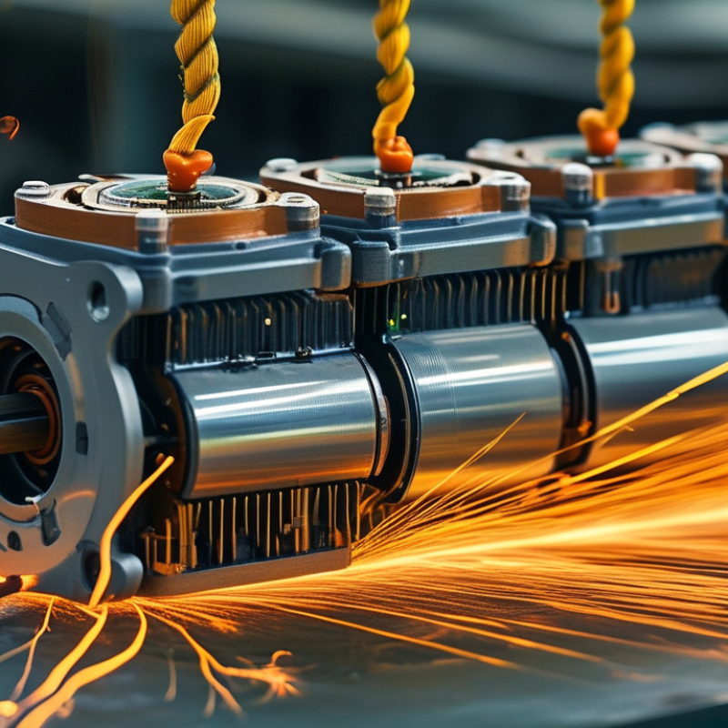
An industrial DC motor is an electromechanical machine that converts direct-current electricity into controlled rotary motion. Its stationary field system creates magnetic flux, while current flows through the armature. The interaction produces torque. In brushed designs, a commutator and carbon brushes switch current direction as the rotor turns. Brushless DC versions use electronic switching instead. The definition sounds simple, but maintenance conditions complicate it.
Industrial DC motors are valued for strong starting torque and wide, responsive speed control. They can drive cranes, rolling equipment, conveyors, hoists, and test machines where sudden loads are common. A controller adjusts armature voltage or field strength, allowing operators to change speed without changing the mechanical transmission. However, brush wear, dust, heat, and poor alignment can reduce reliability. A clean motor room is not guaranteed.
The International Energy Agency’s Energy-Efficiency Policy Opportunities for Electric Motor-Driven Systems estimates that motor-driven systems consume about 43–46% of global electricity. The U.S. Department of Energy’s 2022 Motor Systems Market Assessment also identifies motor systems as a major industrial energy load. These figures explain why efficiency matters beyond the motor nameplate. In practice, engineers should examine the duty cycle, starting frequency, load profile, cooling method, and control losses. A motor may be correctly sized yet inefficient in daily operation. That is easy to miss.
| Data Dimension | Industrial DC Motor Information | How It Works or Why It Matters |
|---|---|---|
| Definition | An electromechanical machine that converts direct-current electrical energy into rotary mechanical energy. | The motor produces continuous rotation when current flows through conductors placed in a magnetic field. |
| Primary Energy Input | Direct current from a battery, DC power supply, rectifier, or controlled industrial drive. | The applied voltage influences motor speed, while the armature current is closely related to torque production. |
| Main Construction | Stator, rotor or armature, field system, commutator, brushes, bearings, frame, shaft, and cooling arrangement. | The stator creates the stationary magnetic field. The armature carries current and develops torque inside that field. |
| Electromagnetic Principle | The force on a current-carrying conductor in a magnetic field creates rotational torque. | Torque is commonly expressed as T = ktIa, where T is torque, kt is the torque constant, and Ia is armature current. |
| Commutation | Mechanical commutation is provided by the commutator and carbon or graphite brushes in a brushed DC motor. | The switching action reverses armature current at the correct rotor position so that torque remains in the same rotational direction. |
| Speed Relationship | Speed generally increases with applied voltage and decreases as load-related voltage drop increases. | A simplified relationship is V ≈ keω + IaRa, where back EMF rises with rotational speed. |
| Typical Speed Range | Approximately 500–3,600 revolutions per minute for many industrial applications; special designs may operate outside this range. | The actual operating speed depends on voltage, field strength, load, motor design, cooling, and the selected drive. |
| Starting Torque | High starting torque is available, particularly from series, compound, and separately excited motor configurations. | At standstill, back EMF is approximately zero, so the drive must limit starting current to prevent excessive heating or mechanical stress. |
| Speed Regulation | Good speed control is possible with a regulated DC drive, feedback sensor, and suitable control loop. | Closed-loop control can compensate for load changes and maintain a more consistent speed than open-loop operation. |
| Common Motor Types | Permanent-magnet, shunt, series, compound, and separately excited DC motors. | Permanent-magnet designs are compact; shunt and separately excited designs offer controllable speed; series designs provide strong starting torque. |
| Power Rating | Industrial units are available from fractional-kilowatt ratings to hundreds of kilowatts, depending on the frame and application. | The correct rating must account for continuous power, overload duration, duty cycle, ambient temperature, altitude, and cooling method. |
| Efficiency | Typically about 75%–95% at or near rated load, with efficiency varying by size, speed, field design, and operating point. | Losses include winding resistance, brush and commutator losses, magnetic losses, bearing friction, windage, and cooling power. |
| Torque-Speed Characteristic | For a separately excited or shunt motor with constant field flux, torque generally decreases as speed rises. | This characteristic supports applications requiring controlled speed and predictable torque, such as conveyors, winders, and machine tools. |
| Regenerative Braking | Possible when the motor operates as a generator and the drive can return energy to the DC supply or braking system. | Regeneration can reduce braking energy waste, but the drive and power system must be designed to manage the returned energy safely. |
| Cooling Methods | Natural ventilation, fan cooling, separately powered ventilation, or liquid cooling for specialized high-power systems. | Adequate cooling prevents insulation damage and allows the motor to deliver its rated output within the specified duty cycle. |
| Maintenance Requirements | Inspection of brushes, commutator condition, bearings, ventilation paths, terminal connections, and insulation condition. | Brushes are wear components and may require periodic replacement, while dust, vibration, misalignment, and overheating can shorten service life. |
| Typical Industrial Applications | Conveyors, cranes, hoists, elevators, rolling equipment, printing machinery, extruders, machine tools, pumps, fans, and traction systems. | DC motors are selected when adjustable speed, high starting torque, frequent acceleration, or regenerative braking is important. |
: An industrial DC motor converts direct-current electricity into controlled rotary motion. Magnetic fields interact with armature current and create torque. It can start strongly. Brushed designs use brushes and a commutator. Brushless designs use electronic switching.
Current enters through carbon brushes and reaches the rotating armature. A segmented commutator reverses current direction as the rotor turns. This keeps torque moving in one direction. Poor brush alignment can cause sparks, heat, and uneven operation.
Key parts include the stator, armature, windings, commutator, brushes, shaft, bearings, housing, and cooling system. The stator creates magnetic flux around the rotor. The shaft transfers torque to connected equipment. Small parts matter.
They operate cranes, hoists, conveyors, elevators, rolling equipment, and printing machines. Mining equipment and marine systems may also use them. They suit machines needing strong starting torque and responsive speed control. Real loads can be harsher than test conditions.
DC motors provide strong starting torque and smooth low-speed control. Controllers can adjust armature voltage or field strength. This may reduce the need for mechanical speed changes. The benefit depends on the complete system, not the motor alone.
Brush wear, dust, heat, vibration, poor alignment, and loose connections can cause problems. Bearing damage may produce noise or excess heat. A clean motor room is not guaranteed. Maintenance conditions deserve honest attention.
Technicians should inspect brushes, commutator surfaces, bearings, terminals, cooling paths, and winding temperature. They should also check vibration and alignment. Sound alone cannot reveal every fault. Measurements are safer than assumptions.
No. Daily efficiency also depends on duty cycles, starting frequency, load changes, cooling, and control losses. A correctly sized motor may still waste energy during real operation. Nameplate selection is only part of the decision. That assumption deserves checking.
Industrial DC Motors are electromechanical devices designed to convert direct electrical energy into controlled mechanical motion. They operate by creating magnetic fields that interact inside the motor, producing torque and rotation. This process allows operators to adjust speed, direction, and starting performance, making these motors suitable for demanding industrial systems. Their main components typically include a stator, rotor or armature, commutator, brushes, shaft, bearings, and housing. Each part contributes to generating motion, transferring power, or maintaining reliable operation.
Common types include brushed DC motors, permanent-magnet DC motors, series-wound motors, shunt-wound motors, and compound-wound motors. They are selected according to required torque, speed stability, control accuracy, and operating conditions. Industrial DC Motors are widely used in conveyors, cranes, elevators, rolling equipment, machine tools, pumps, printing systems, and automated production machinery. Although modern control technologies continue to develop, DC motors remain valuable where strong starting torque, responsive speed control, and dependable performance are essential.