
Choosing a motor control system starts with the machine, not the catalog. A conveyor moving heavy boxes has different needs from a small pump or a positioning stage. The right choice affects speed stability, starting torque, energy use, and service life. DC Motor Control Systems range from simple voltage controllers to closed-loop drives with sensors and adjustable protection.
Begin with the motor’s nameplate. Check its rated voltage, current, power, and speed. Then consider how the load behaves during startup and operation. A fan usually needs modest starting torque, while a loaded conveyor may demand much more. Frequent starts, abrupt stops, or changing loads can also shape the decision. Small details matter.
A brushed motor may suit a straightforward, cost-conscious installation, but its brushes need periodic inspection. A brushless motor can reduce routine wear, though its controller and setup may be more complex. Open-loop control can be adequate when speed precision is not critical. For tighter speed regulation, feedback from an encoder or Hall sensors can help the drive respond to changing loads. The extra hardware is not always worthwhile.
Also compare the controller’s continuous and peak current ratings, thermal limits, protection features, and installation environment. A compact drive may fit a control cabinet neatly, yet still overheat without proper ventilation. Confirm that the control interface, supply, and wiring match the motor and application. Manufacturer documentation is the best source for these limits; assumptions based on appearance can lead to poor results. In practice, testing under the real load often reveals issues a datasheet cannot. No selection is perfect. A clear checklist, careful review, and a small amount of application testing can help narrow the options before purchase.
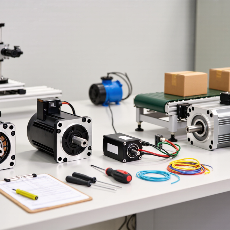
Before choosing a DC motor control system, describe the motion the machine must perform. Does it run at one steady speed, accelerate smoothly, or reverse direction every few seconds? A conveyor carrying light packages has different needs from a positioning table that must stop within a few millimeters. Be specific. “Fast” is not a usable requirement.
Record the motor’s load, desired speed range, acceleration time, and duty cycle. Note whether the load changes during operation, such as a lift becoming heavier as it rises. Measure the available supply voltage and estimate peak current during startup, not just the normal running current. These details help determine whether the controller can deliver enough torque without overheating. A useful test is to observe the motor through a full operating cycle. Small surprises matter.
Set acceptable limits for speed variation, stopping distance, noise, and temperature. If the motor must hold position while stationary, confirm how long it needs to hold and whether the controller must manage heat during that period. Build in margin, but avoid oversized assumptions. I have seen requirements written too loosely, then revised after a prototype struggled with a real load. That is not a failure; it is a reminder to test the actual motion, not just the motor on a bench.
| Application Profile | Motion Requirement | Typical Performance Targets | Feedback to Consider | Control System Features to Prioritize | Suitable Control Approach |
|---|---|---|---|---|---|
| Small fan or blower | Continuous, mostly one-direction rotation; gradual speed changes | Steady speed; low-to-moderate starting torque; quiet operation | Open-loop operation may be adequate when load and speed accuracy requirements are modest; add speed feedback if consistent speed is important | Thermal protection, current limiting, smooth startup, and efficient operation over the expected speed range | DC voltage or PWM speed control; closed-loop speed regulation when required |
| Conveyor or powered roller | Continuous motion, frequent starts and stops, or operation under changing load | Good low-speed torque; controlled acceleration and deceleration; repeatable running speed | Encoder or Hall-sensor feedback where speed regulation or motion monitoring is needed | Adjustable ramps, overload protection, speed regulation, and a driver rated for startup and load currents | PWM drive with closed-loop speed control for variable-load applications |
| Positioning axis or actuator | Move to defined positions; stop accurately; repeat moves | Position accuracy and repeatability depend on the mechanism, sensor resolution, backlash, and load | Encoder, potentiometer, or other position sensor matched to the required accuracy and travel | Position feedback, programmable motion profiles, limit handling, and braking or holding provisions when needed | Closed-loop position control, often combined with inner speed or current control |
| Robotic joint or mobile platform | Frequent direction changes; dynamic speed and torque demands | Fast response; controlled acceleration; adequate peak torque without exceeding motor or driver limits | Encoder feedback for speed and position; current sensing for torque estimation and protection | Four-quadrant operation, current limiting, configurable control loops, and coordinated command handling | Bidirectional closed-loop control with speed or position commands and current regulation |
| Pump or compressor | Continuous rotation, sometimes with variable speed or changing pressure and flow demand | Reliable starting under the expected load; stable operation at the required operating points | Speed feedback when process consistency requires it; pressure or flow sensing may provide application-level feedback | Overcurrent and thermal protection, suitable startup behavior, and compatibility with the required supply voltage | PWM speed control; closed-loop speed or process control where the application calls for it |
| Battery-powered portable device | Intermittent operation with changing battery voltage and variable load | Low power consumption; predictable response; adequate peak output during startup | Speed or position feedback when needed for consistent output; battery-voltage and current monitoring | Low standby consumption, undervoltage handling, current limiting, and thermal protection | Efficient PWM drive with feedback selected according to speed or positioning requirements |
| Selection check: Verify motor voltage, continuous and peak current, load torque, speed range, duty cycle, acceleration, braking needs, feedback compatibility, and environmental conditions before choosing a controller. | |||||
Compare rated voltage, continuous current, peak current, stall current, and torque requirements. Running current alone is insufficient. Acceleration can briefly demand much more power.
A motor starting under load may pull heavy current for a short time. A 24 V supply can dip during startup. That dip may cause resets, noise, or weak torque.
It usually provides precise speed regulation. Still, test switching frequency, heat, and electrical noise. The motor may sound different at various frequencies.
Record voltage, current, speed, torque, and temperature. Test no load, half load, and rated load. Use calibrated probes and suitable mechanical measurement equipment.
Test acceleration, braking, reversal, and sudden load changes. Measure speed error during every event. Do not test only steady running.
Check the motor case and controller temperature after warm-up. A hot case after ten minutes deserves attention. Leave thermal headroom instead of sizing at the limit.
Long cables can create voltage drop and electrical interference. Poorly shielded feedback wiring may produce unstable readings. Dust, weak airflow, friction, and supply variation also matter.
Review peak current, thermal rise, response time, noise, and fault recovery. Repeat tests after warm-up. If results conflict, inspect the measurement setup before approval. The catalogue may be right, but the installation may still fail.
Choosing the right DC Motor Control Systems begins with a clear understanding of the application’s motion and performance requirements, including desired speed, torque, precision, and operating conditions. The controller should be compatible with the motor’s electrical characteristics and the available power supply. Comparing speed, torque, and position control methods helps identify the approach that best fits the application.
Selection also depends on protective features, environmental conditions, and how easily the controller will integrate with the wider system. After narrowing down the options, test the complete setup under representative operating conditions. Evaluating performance, reliability, and responsiveness can reveal whether the chosen system meets requirements and help guide adjustments before deployment.