
Industrial machines rarely work under ideal conditions. A conveyor may start with a loaded belt; a press may demand strong torque at low speed. In these settings, High Torque DC Motors can offer controllable starting performance and straightforward integration, but the right choice depends on more than a headline torque rating. Buyers must compare continuous and peak torque, operating speed, duty cycle, voltage, cooling, and maintenance needs.
The U.S. Department of Energy’s 2014 United States Industrial Electric Motor Systems Market Opportunities Assessment reports that motor-driven systems account for about 68% of electricity use in U.S. manufacturing. That figure covers industrial motor systems broadly, not DC motors alone. Still, it shows why efficiency and correct sizing deserve attention. An oversized motor can waste energy; an undersized one may overheat under repeated starts. Heat matters.
Austin Hughes, author of Electric Motors and Drives, is a recognized reference in motor engineering. A useful principle from his engineering approach, paraphrased here, is that torque must be assessed alongside speed and operating conditions. This guide compares leading high-torque DC motor options by practical measures, including output, control, durability, and application fit. Specifications vary by manufacturer and test conditions, so published ratings should be checked against the actual load. A catalog number cannot tell the whole story. Shortlisting motors is only a starting point; real installation conditions may expose trade-offs that a datasheet misses.
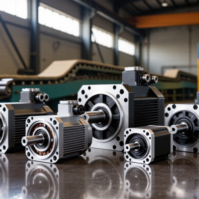
A high-torque DC motor turns electrical input into rotation through the interaction between current-carrying conductors and a magnetic field. When current flows through the armature windings, magnetic forces act on opposite sides of the rotor and create turning force, or torque. The commutator reverses current direction as the rotor turns, helping torque continue in the same rotational direction. In practical terms, more current can produce more torque, provided the motor and drive can safely handle the added heat. That’s the basic mechanism.
At startup, a motor may need especially high torque to overcome a conveyor’s resting load or move a heavy indexing table. As speed rises, back electromotive force builds and limits current, so available torque usually changes with operating conditions. A gearbox can multiply output torque while reducing speed, but it does not create free power; losses appear as heat and friction. Small detail, often missed. Selecting a motor means checking the load profile, acceleration time, duty cycle, and starting frequency, not just a peak-torque figure.
A lifting fixture that starts and stops repeatedly can heat a winding faster than a steady-running fan. Use current, temperature, and shaft-speed measurements during realistic trials, then compare them with the motor’s rated limits. An oversized motor can still perform poorly if its controller, cooling, or gearing is mismatched. A temperature probe near the winding and a current log can reveal overload before a shutdown occurs.
| Motor Configuration | How It Produces Torque | Speed and Motion Characteristics | Typical Industrial Uses | Selection Considerations |
|---|---|---|---|---|
| Series-Wound Brushed DC Motor | The field winding is connected in series with the armature. At startup, high armature current also creates a strong magnetic field, producing high starting torque. | Speed can vary substantially with load. A series motor can reach dangerously high speed if operated without a load. | Traction drives, winches, hoists, and other applications that need strong starting pull. | Use appropriate current limiting and speed control. Avoid unloaded operation unless the motor and drive system are specifically designed for it. |
| Shunt-Wound Brushed DC Motor | The field winding is connected in parallel with the armature, so field current is relatively independent of armature load current. | Provides comparatively steady speed as load changes. Starting torque is generally lower than that of a comparable series-wound motor. | Conveyors, machine tools, and process equipment requiring relatively consistent speed. | Check starting-load requirements and drive limits. Speed can be adjusted by changing armature voltage or field current within the motor’s ratings. |
| Compound-Wound Brushed DC Motor | Combines series and shunt field windings, bringing together strong starting torque and improved speed regulation compared with a series motor. | Offers a practical balance between starting pull and steadier operating speed; the exact response depends on the winding design. | Elevators, presses, conveyors, and machinery with changing loads and frequent starts. | Confirm the compound winding arrangement and the required torque-speed curve with the motor specifications. |
| Separately Excited Brushed DC Motor | The field winding has a separate supply, allowing field current and armature current to be controlled independently. | Offers a broad controllable speed range. Field weakening can raise speed above the base-speed region while reducing available torque. | Industrial drives needing adjustable speed, controlled acceleration, or a wide operating range. | Requires a suitable field supply and coordinated drive control. Observe rated current, voltage, and field limits. |
| Permanent-Magnet DC Motor (PMDC) | Permanent magnets provide the field flux. With the field approximately fixed, motor torque is broadly proportional to armature current. | Compact and straightforward to control by adjusting armature voltage or using pulse-width modulation (PWM). Available torque is limited by thermal and current ratings. | Compact industrial actuators, powered mechanisms, and equipment requiring simple DC speed control. | Check continuous and peak current, winding temperature limits, and the effects of heat on the motor’s magnets. |
| DC Gearmotor | A DC motor drives a gearbox. Gear reduction trades output speed for output torque; actual output torque is lower than the ideal value because of gearbox losses. | Provides slower output motion and higher torque at the gearbox shaft than the motor shaft. Backlash and efficiency depend on the gear design. | Material handling, positioning systems, powered doors, and low-speed machinery. | Match the gearbox ratio, output-shaft load, duty cycle, and required positioning accuracy to the application. |
| Electronically Commutated DC Motor (BLDC) | Permanent magnets on the rotor interact with stator windings switched by an electronic controller to produce torque. | Supports controlled speed and torque with no mechanical brushes. Performance depends on the controller, motor design, and feedback method. | Industrial pumps, fans, automation equipment, and drives requiring electronic speed control. | Choose a compatible controller and confirm commutation, cooling, torque, and speed requirements for the intended duty cycle. |
| How force and motion are produced: Current in a motor’s conductors interacts with magnetic flux to create electromagnetic torque. In a rotating motor, torque at the shaft produces motion; when a shaft or wheel applies that torque at a radius, it can create linear force. In simplified form, shaft power is torque multiplied by angular speed, and gearbox reduction increases output torque while reducing output speed, subject to mechanical losses. Actual performance depends on the motor, controller, cooling, load, and duty cycle. | ||||
Current flows through the armature windings inside a magnetic field. The resulting force turns the rotor. A commutator helps keep torque moving in the same direction.
It must overcome a resting load, such as a loaded conveyor or heavy indexing table. Startup demand can be brief but substantial. Small detail, easily missed.
A gearbox can increase output torque while reducing speed. It also adds friction and heat, so it does not create extra power.
Brushed permanent-magnet motors can suit compact conveyors and actuators, but their brushes wear over time. Frequent starts may increase maintenance needs.
They can provide strong starting torque for heavy loads. However, speed may rise sharply when the load falls, so suitable control is important.
They use electronic commutation rather than mechanical brushes, reducing routine brush maintenance. Drive settings and cooling still need attention. Not maintenance-free.
Log current and shaft speed during realistic operation. Measure winding temperature when possible, especially on a fixture that starts and stops repeatedly.
Check continuous and peak torque, speed range, duty cycle, voltage, cooling, and mounting details. Ask how published figures were tested. A catalog number alone can mislead.
Not necessarily. A mismatched controller, gearbox, or cooling setup can still cause poor performance. Test under the real load, then reassess. The first estimate may be wrong.
High Torque DC Motors convert electrical energy into powerful, controllable rotation, making them useful wherever industrial equipment must move heavy loads or start under demanding conditions. Their force comes from the interaction of magnetic fields and current, while speed and direction can be adjusted to suit different tasks. Common options include brushed and brushless designs, each offering distinct trade-offs in control, efficiency, durability, and maintenance needs.
Comparing motors involves more than looking at torque: rated speed, power, duty cycle, operating environment, and control requirements also matter. The right choice depends on the application, such as conveyors, lifting systems, or processing machinery. Proper installation, suitable drive settings, and routine checks of connections, cooling, and wear help support reliable operation and extend service life. By considering performance and practical operating needs together, facilities can select a motor that delivers dependable motion without unnecessary energy use or maintenance.