
Technical insights, expert guides, and industry news on DC motors, AC motors, and drive technology.
Selecting Industrial DC Drives is not simply a matter of matching voltage and horsepower. The right choice affects motor life, production stability, energy use, and maintenance costs. In a real plant, a drive may operate beside hot furnaces, dusty conveyors, or equipment with frequent speed changes. These conditions can expose weaknesses that a catalog rarely shows. Engineers should examine motor ratings, load behavior, braking requirements, control accuracy, and available installation space before approving a model.
Small details matter. A drive that works well on a lightly loaded test bench may struggle during conveyor startup. Ambient temperature, ventilation, cable length, and electrical noise can also change performance. Review the manufacturer’s datasheet carefully. Confirm overload capacity, feedback options, protection functions, and service support. Qualified technicians should verify wiring and commissioning procedures against applicable standards and site requirements. Experience helps, but assumptions can still cause expensive mistakes. I have seen specifications look suitable until the actual load profile revealed repeated current peaks. That is why this guide focuses on practical checks rather than impressive features. The ten tips will help readers compare Industrial DC Drives with clearer judgment, reduce avoidable selection errors, and build a more dependable drive system. Some recommendations may require adjustment for older motors or unusual processes. That uncertainty deserves attention, not dismissal.
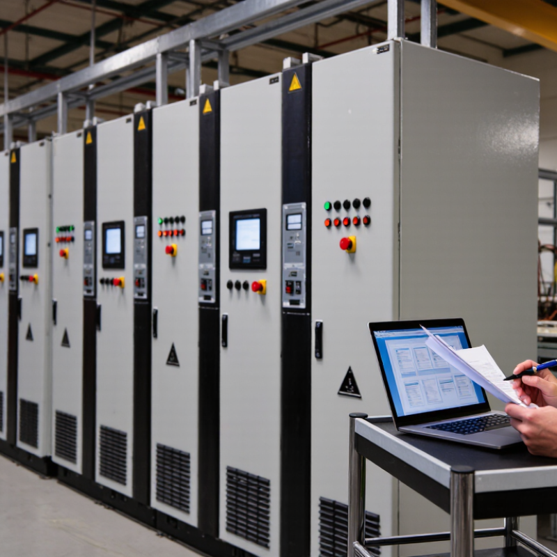
Industrial DC drives are electronic control systems that regulate the speed, torque, and direction of DC motors. They adjust motor voltage and current through power electronics. A feedback sensor can compare actual speed with the target speed. The controller then corrects the difference.
Unlike a simple motor starter, a DC drive supports smooth acceleration and controlled stopping. This reduces mechanical shock on gears, belts, and couplings. Common applications include conveyors, cranes, hoists, rolling mills, extruders, printing machines, and older production lines. A conveyor carrying glass panels may need gentle starting to prevent sudden movement. A crane may require precise low-speed torque while lifting a heavy load.
In practical selection, engineers check motor voltage, continuous current, overload capacity, braking method, and enclosure rating. Ambient temperature and dust also affect reliability. Regenerative braking may return energy to the electrical system, but it requires compatible system design.
I have seen installations fail because the drive was sized only for normal current. Short overload periods were ignored. That was a costly assumption.
Maintenance teams should also confirm spare parts, cooling airflow, cable condition, and feedback compatibility. A technically correct drive can still perform poorly when ventilation is blocked or tuning is rushed.
Selection is rarely perfect on the first attempt. Field measurements often reveal details that a catalog cannot.
Choosing an industrial DC drive starts with the motor nameplate, not the machine’s marketing label. Record rated voltage, full-load current, horsepower, base speed, and field requirements. The drive’s continuous output current should meet or exceed the motor’s rated current. Its voltage range must suit the armature and field circuits. A 10% current margin is often practical, but the machine duty may require more.
Check acceleration and overload demands carefully. Conveyors, hoists, and crushers can draw several times rated torque during starting. Compare the drive’s short-term overload rating with the motor’s locked-rotor current and load profile. Also verify regenerative braking capacity. A drive that handles running power may still trip during a fast stop.
IEC 61800-5-1 provides safety requirements for adjustable power drive systems, while NEMA MG 1 offers motor application guidance.
Power alone can mislead. The U.S. Department of Energy’s Motor Systems Market Assessment reports that motor-driven equipment uses roughly 70% of industrial electricity in the United States. Small rating errors can therefore create persistent losses. Check ambient temperature, enclosure airflow, altitude, and switching conditions. Derating may be necessary above standard conditions.
In field commissioning, I have seen a seemingly correct drive overheat because cabinet ventilation was ignored. The calculation looked fine. The installation was not.
Review cable voltage drop and protection settings, too. A cautious margin is useful, but excessive oversizing can reduce control quality and increase cost.
10 Tips for Choosing Industrial DC Drives
Control mode should match the machine’s real workload, not only its nameplate. A speed-control mode suits conveyors, winders, and pumps requiring steady output. Torque control is better for tension-sensitive processes, where sudden load changes can damage material. In my field experience, commissioning often exposes a mismatch between the selected mode and the production cycle. It looked correct on paper.
Feedback determines how confidently the drive responds. An armature-voltage signal is simple and economical, but load changes can cause noticeable speed drift. Tachometer or encoder feedback improves regulation, especially during low-speed operation and rapid acceleration. The International Energy Agency reports that electric motor systems consume about half of global electricity, making efficient control a practical concern, not a minor specification. Check sensor resolution, cable shielding, and failure detection before approval.
Speed regulation should be tested across the entire operating range. Do not judge it only at full speed. Record overshoot, recovery time, and steady-state error during start-up and sudden loading. The U.S. Department of Energy identifies motor-driven systems as a major portion of industrial electricity use, so small control losses can become expensive. A useful target is stable speed within the process tolerance, rather than the smallest advertised percentage. That distinction is easy to miss. Also, leave room for imperfect sensors and aging components. Real factories are rarely as clean as test benches.
| No. | Evaluation Area | Relevant Technical Data | What to Check | Selection Guidance |
|---|---|---|---|---|
| 1 | Motor and Supply Compatibility | Armature voltage, armature current, field voltage, field current, and AC input voltage must match the motor and electrical system. | Verify the motor nameplate values and confirm that the drive's continuous and peak current ratings are adequate. | Select a drive with an armature voltage rating at or above the motor rating and continuous current capacity above the calculated operating current. |
| 2 | Control Mode | Common modes include armature-voltage control, current or torque control, and field control for speeds above base speed. | Determine whether the process requires basic speed control, rapid torque response, tension control, or coordinated motion. | Use armature-voltage control for straightforward applications; use current or torque control when load response and precise torque are important. |
| 3 | Feedback Selection | Typical feedback devices include tachogenerators, incremental encoders, and resolvers. Feedback resolution and signal type affect regulation quality. | Check pulse format, maximum input frequency, voltage level, direction signal, and compatibility with the motor shaft and coupling. | Choose encoder feedback for accurate low-speed regulation and repeatability; use a tachogenerator where legacy compatibility is required. |
| 4 | Speed Regulation | Open-loop regulation is affected by load changes. Closed-loop systems can commonly achieve approximately ±0.1% to ±1% speed regulation, depending on feedback and tuning. | Define the allowable speed error during acceleration, steady-state operation, and load changes. | For stable speed under changing load, select a closed-loop speed regulator and verify the stated regulation accuracy under the actual operating range. |
| 5 | Speed Range and Field Weakening | A separately excited DC motor normally provides constant torque below base speed and approximately constant power above base speed when field weakening is used. | Identify the minimum and maximum operating speeds, required overspeed margin, and available motor field range. | Confirm that the drive supports the required field-current control and that the motor is approved for the intended maximum speed. |
| 6 | Acceleration, Deceleration, and Current Limit | Adjustable ramps control acceleration and deceleration. Current limiting protects the motor and drive while controlling torque during transients. | Calculate load inertia, starting torque, stopping time, and the frequency of starts, stops, and reversals. | Select sufficient current capacity and configurable ramp profiles; avoid using current limit as a substitute for correct mechanical sizing. |
| 7 | Regenerative and Four-Quadrant Operation | Four-quadrant operation allows forward and reverse motoring as well as forward and reverse braking. Regenerative drives can return braking energy to the AC supply. | Check whether the load can drive the motor during lowering, unwinding, overhauling, or rapid deceleration. | Use a regenerative or four-quadrant configuration when frequent braking occurs; otherwise, a braking resistor or controlled coast may be sufficient. |
| 8 | Overload and Duty Rating | Drive ratings commonly distinguish continuous current from short-term overload current. Motor thermal capacity depends on cooling, speed, load profile, and ambient temperature. | Compare the drive overload duration and percentage with the machine's peak torque and duty cycle. | Choose based on the RMS and peak current demand, not only the motor's nominal horsepower or kilowatt rating. |
| 9 | Control, Communication, and Safety | Useful interfaces may include analog speed references, digital inputs, relay outputs, fieldbus communication, fault relays, and safe stop functions where supported. | Confirm PLC compatibility, reference signal range, network protocol, fault diagnostics, emergency-stop architecture, and required safety functions. | Select interfaces that match the existing control system and verify safety functions against the machine risk assessment and applicable standards. |
| 10 | Installation Environment and Maintainability | Important factors include ambient temperature, humidity, altitude, enclosure rating, cooling method, electrical clearance, EMC conditions, and access for service. | Check derating requirements, ventilation, dust or corrosive exposure, cable routing, spare parts, parameter backup, and diagnostic tools. | Choose an enclosure and cooling arrangement suitable for the site, and prioritize clear diagnostics and readily replaceable components for critical equipment. |
Note: Performance ranges are typical engineering references. Final selection should be verified against the motor nameplate, complete load profile, installation conditions, and the drive manufacturer's technical documentation.
Choosing an industrial DC drive starts with the room around it, not the catalog page. Record ambient temperature, humidity, dust, vibration, and corrosive vapors near the cabinet. A dusty workshop needs suitable enclosure protection and filtered airflow. Moisture is often underestimated. Condensation can damage terminals overnight. Check altitude too, because thinner air reduces cooling performance. Use the drive’s technical data, and confirm ratings with a qualified engineer.
Safety Requirements Safety requirements should be observed before wiring begins. Provide isolation, overcurrent protection, grounding, and an emergency stop circuit suited to the machine. Do not treat a software stop as the only safeguard. Stored electrical energy can remain after power removal, so verify discharge times and test with approved instruments. Keep cables separated from sensitive control wiring to reduce interference. Label terminals clearly. I have seen rushed labeling turn a simple fault into hours of downtime. That lesson is practical, though one inspection cannot replace a full risk assessment.
Leave enough clearance for ventilation, maintenance, and safe access to disconnecting devices. Mount the drive on a rigid, clean surface, away from heat-producing equipment. Check cable lengths, motor compatibility, braking demands, and earthing arrangements before commissioning. Tighten connections to the specified torque. Loose terminals create heat. Test at low speed first, then increase the load gradually while recording temperature and current. If readings differ from predictions, pause and investigate rather than adjusting limits blindly. Installation drawings should show actual field changes, not just the original plan.
Choosing an industrial DC drive is rarely about purchase price alone. In a plant audit, energy losses often appeared during partial-load operation, not at rated output. Compare efficiency across normal speed ranges, braking cycles, and hot cabinet conditions. Ask for measured curves, not rounded catalogue figures. A one-percent gain can matter when a conveyor runs eighteen hours daily. Still, efficiency claims need site data. That part is often missed.
Maintenance costs grow quietly. Check brush access, cooling fan life, terminal layout, and fault-history tools before approval. A drive that opens quickly can reduce a midnight repair from two hours to thirty minutes. Inspect replacement intervals and the availability of compatible control boards. Keep critical spares in a clean, labeled cabinet. Some teams overstock expensive parts, while others keep none. Both choices deserve review. Support should include commissioning guidance, remote diagnostics, manuals, and realistic response times. A phone number alone is not support.
Calculate total cost over five to ten years. Include electricity, planned downtime, training, spare parts, software access, and disposal. Compare service contracts carefully; low upfront fees may hide travel charges or exclusions. Ask whether technicians understand your motor, load profile, and plant environment. Test escalation procedures before a failure occurs. Record assumptions in writing, because forgotten assumptions become invoices. A pilot installation can expose nuisance trips, heat buildup, or confusing alarms. It may delay procurement slightly. That delay can prevent a costly mistake.
It controls a DC motor’s speed, torque, and direction. It adjusts voltage and current through power electronics. A feedback sensor can compare actual speed with the target.
A drive supports smooth acceleration and controlled stopping. This reduces shock on gears, belts, and couplings. A starter usually offers less control.
Common uses include conveyors, cranes, hoists, rolling mills, extruders, and printing machines. Older production lines may also need them. A glass-panel conveyor needs gentle starting.
Check motor voltage, continuous current, overload capacity, braking method, and enclosure rating. Also review temperature, dust, airflow, cables, and spare parts. Normal current alone is not enough.
Speed control suits conveyors, winders, and pumps needing steady output. Torque control suits tension-sensitive processes. The machine cycle matters more than its nameplate.
Feedback helps the drive correct speed errors during load changes. Armature-voltage feedback is economical but may drift. A tachometer or encoder usually improves low-speed control.
Test the full operating range, not only maximum speed. Record overshoot, recovery time, and steady-state error. Test sudden loading too.
Check brush access, cooling fan life, terminal layout, and fault-history tools. Blocked ventilation can cause heat buildup and nuisance trips. Cooling is easy to underestimate.
Include electricity, downtime, training, spare parts, software access, and disposal. Review costs over five to ten years. A cheap purchase can become expensive.
Yes, a pilot can reveal heat buildup, nuisance trips, and confusing alarms. Field measurements may contradict catalogue expectations. The first choice may still be wrong.
Choosing the right Industrial DC Drives begins with understanding how they regulate DC motor speed, torque, and direction in applications such as conveyors, hoists, machine tools, printing equipment, and material-handling systems. Buyers should match the drive’s rated voltage, continuous and peak current, and power capacity with the motor and expected load. It is also important to evaluate available control modes, feedback options, acceleration and deceleration settings, and speed regulation accuracy to ensure stable performance under changing operating conditions.
Before making a decision, review the installation environment, including temperature, humidity, dust, vibration, enclosure requirements, ventilation, wiring, and safety features. Efficiency should be considered alongside maintenance needs, service accessibility, technical support, spare-part availability, and the expected operating life. A dependable drive may offer greater value through reduced downtime and energy use, even if its initial purchase cost is higher. Comparing total ownership cost will help users select a practical, safe, and reliable solution for long-term operation.